Historically, naval architects have used flexible battens, or splines to draw smooth two-dimensional curves. By fixing the end points of the spline and applying a load at one or more points along the spline, a curve is created that can then be traced onto a drawing. The curve's smoothness will depend on the stiffness of the spline and the exact placement of the loads, but as long as a few simple rules are followed, the resulting curvature will be smooth.
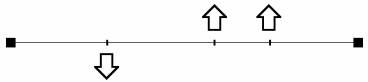
The spline will initially lie straight on the drawing board.
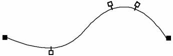
After dragging the spline at a number of points, the natural stiffness of the spline will result in the smooth curve used for drawing.
To generate its curves, Maxsurf uses a mathematical equation, the B-spline, which is analogous to this procedure. As with drafting splines, curves are defined by the position of their end points, the location and number of controlling points along the curve, and the stiffness of the spline.
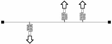
Rather than a row of weights that sit along the spline, Maxsurf's curves are shaped by control points, which can be thought of as being attached to the spline by springs. When the control points are moved the inherent stiffness of the spline and the springs combine to keep the curve smooth. An obvious effect of this is that the control points do not lie on the curve created but rather the curve is attracted toward the position of the control points.
Thus, a spline, which is initially straight, is dragged to a new shape at a number of points.
The resulting curve is smooth with only the two end control points lying on the curve.
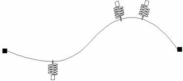
By moving the controlling points about, you can bend the spline to a given shape. The curvature of the spline would be free from irregularities, due to the elasticity of the springs and the stiffness of the spline itself. If the spline were made more flexible or stiffer, the curvature would correspondingly increase or decrease.
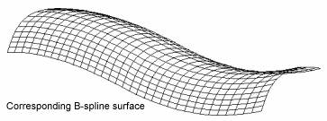
Although this is a two-dimensional example, Maxsurf uses an analogous procedure to generate its splines in three dimensions to form a surface.
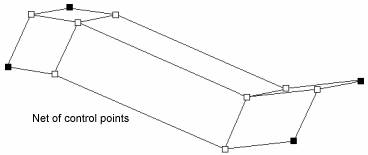
Just as a row of two-dimensional control points can define a two-dimensional curve, a network of three dimensional control points can define an entire three-dimensional surface.
If you consider a network of three-dimensional controlling points, you can imagine that splines could be held along and across the net, hence defining a surface. Maxsurf does just this, and uses a network of three dimensional control points to generate a surface.
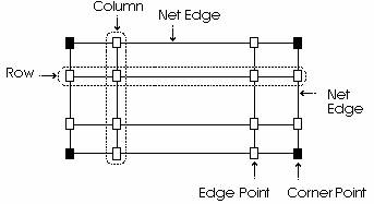
The net is formed by rows and columns of control points and has four edges and four corners. Up to 25 rows of control points may be used, depending on the complexity of the desired surface. Note that this limit is for manually defined surfaces, those surfaces which have been imported from other CAD programs (in IGES format) may have any number of control points. There is no restriction on the number of columns of control points. The surface may have different stiffness in the row and column directions.
A surface is created by the generation of splines in three dimensions from the control points that make up the net.
The effect a control point has on a surface depends firstly on whether it is a corner, edge or internal control point.
· Corners of a surface are defined exactly by the position of the corresponding corner of the net.
· Edges are defined only by the control points on the corresponding edge of the net.
· Internal points of the surface may be influenced by many or all of the control points in the net.
Any number of independent surfaces may be used in the definition of a design in Maxsurf, each with its own control point net. A control point only influences the surface to which it belongs. The only exception to this is the case where two surfaces are bonded together along a common edge. If a control point is moved on a bonded edge it will affect both of the surfaces sharing the bonded edge.
When using Maxsurf, remember that you are changing the position of control points relative to one another in the net to achieve a desired change in the surface. Maxsurf will then recalculate and display the new surface shape. Just as in the spring analogy you may only change the shape of a surface by moving control points in the net rather than directly moving the surface itself.
More information on NURB surfaces can be found in the Working with Surfaces section on page 90.